
Design and implementation of the wooden structure: TAROS NOVA s.r.o.
Project documentation and technical solution: Ing.arch. Pavel Železný, Ing. Zdeněk Vejpustek, Ing.arch. Miroslav Slíva, Ing. Karel Mikeš, Ph.D., Brno University of Technology, CTU Prague and Bc. Jan Valíček, TAROS NOVA s.r.o.
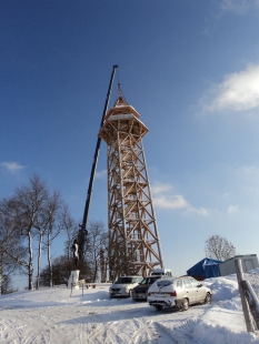
Address: Bohdaneč near Kutná Hora, Czech Republic; GPS: Loc: 49°46'59.799"N, 15°13'54.669"E
Implementation: 2010
Implementation duration: 3 months; design preparation time: 4 months
Volume of logs: 145 m3; volume of sawn timber: 45 m3; weight of steel: 33 t
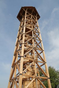
Number of floors: 9 + roof
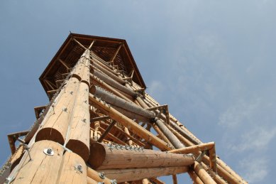
Height: 50.7 m; base dimensions: 8.2 x 8.2 m
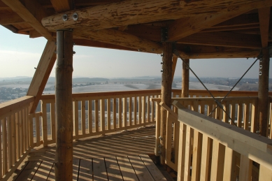
Height of the observation platform: 40.6 m; area of the observation platform: 41 m2
Number of steps: 217
New lookout tower Bohdanka in the village of Bohdaneč
Publisher
Pavlína Drbálková
24.11.2011 09:00
Pavlína Drbálková
24.11.2011 09:00
 |
The observation platform, situated 40.6 m above ground, allows visitors to see the ridges of the Krkonoš and Šumava mountains in good weather conditions. The total height of the tower is 50.7 m, making it one of the tallest structures made from sections of wooden logs in the world.
Basic Description
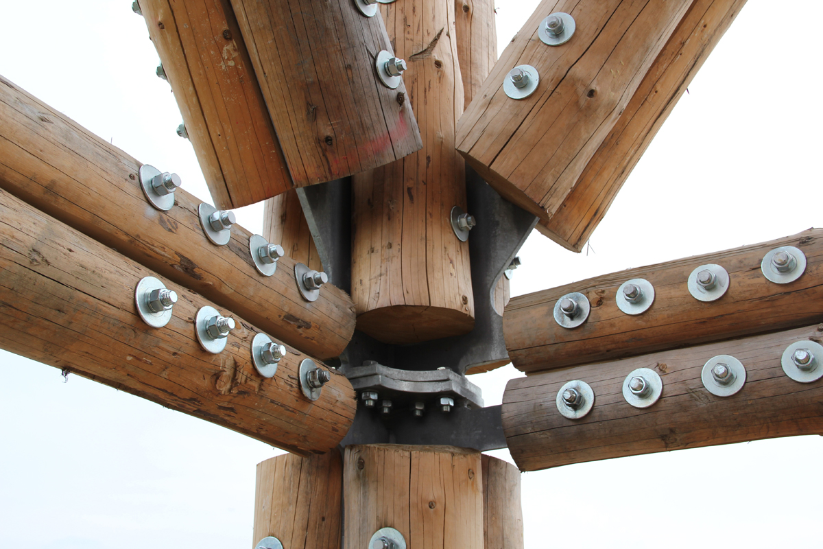
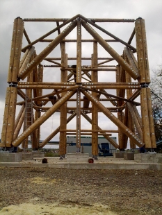
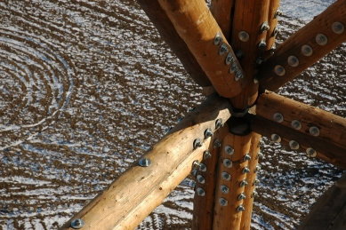
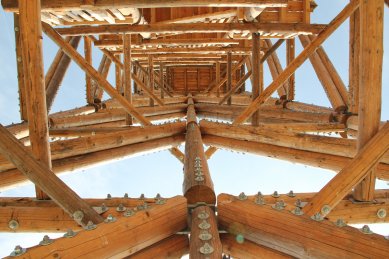
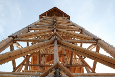
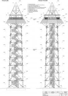
Design, Joints, Assembly, ProtectionAt first glance, it is evident that the primary load affecting the tower comes from wind, which, in combination with icing, creates extreme forces on the individual rods and foundations. Great emphasis was placed on the foundation because it was necessary to transfer the tensile forces acting on the corner columns. According to the computational model, these forces reach values around 2800 kN, so relying solely on the gravitational weight of the foundations is no longer economically viable. For these reasons, the foundation slab was secured with groups of micropiles under the most stressed areas. Due to these forces, it is complicated to use logs for the corner columns of the first three floors. Theoretically, it would be possible to transfer these forces with four pieces of 400 mm in diameter, but the implementation of the joint limits this case. Therefore, steel columns were used for the first three floors, with wood serving only as additional reinforcement.
The main wooden elements are connected using steel elements, and the structure is dynamically loaded, so special attention was needed in designing the steel details to eliminate notches and the occurrence of fatigue failures. The natural frequency of the tower and forces resulting from the oscillation of the tower were determined using computational software. It was found that the structure is not very sensitive to the dynamic load component. However, local oscillation of individual rods may occur, which was addressed in the design of the joint. Given the placement of the structure outdoors, the effects of temperature fluctuations must be taken into account. For this reason, the effects of these temperature changes were verified, as they must be considered due to the different thermal expansion of the materials used in the structure. In the computational model, joints were modeled as flexible with an initial slip of 1 mm. A nonlinear calculation encompassing all influences was necessary.
Execution of Joints
Great attention was paid to the execution of the main joints of the wooden elements. Since this is a dynamically loaded structure, it was necessary to execute the joints in such a way that they were as insensitive as possible to dynamic loads and the alternation of tensile and compressive forces. During the design of the structure, several variants were considered. After consultations with experts, a joint was designed where the primary load-bearing function is fulfilled by a tight bolt with a diameter of 24 mm made from quality 8.8 steel. The decisive mode of failure at these joints is the occurrence of three plastic hinges in the bolt. A locally reinforcing element at the point of greatest stress in contact with the wooden bolt was chosen to be a grooved plate with 2 mm thick spikes.
Another problem that could impair the joint's function is the emergence of drying cracks at the point of contact between the bolt and the wood. Therefore, the critical points were reinforced using fully threaded screws. Although the corner columns on the first three floors were replaced with steel, the design force acting in the joint of the corner column on the fourth floor reaches a value of 1220 kN. To transfer this force, the joint at the corner column was designed as an eight-shear joint. This allowed the length of the joint to be limited so that it could be placed within one module. As the height increases and forces decrease, the number of connecting elements is gradually reduced.
 |
Quality of Wood
The quality requirements increased with the height, and the best properties were used for the most stressed parts of the structure. Each piece had to be measured, classified, and its placement in the structure determined based on certain parameters. Critical values regarding knottiness were established for joints based on the method of implementation, the location of the material in the exterior, and other aspects concerning quality. A forensic expert report on the quality of the wood was prepared for this reason, as similar construction types typically have no usual literature available to obtain information about the quality of wood needed for such construction. The logs used as the main structural material are not very common in buildings of this size.
Therefore, the expert report concerning the wood quality was prepared, which established limit values for convergence, twist, humidity, knottiness, and other parameters based on the material's placement outdoors and the joint execution method. Each piece had to be measured, classified, and its placement in the structure determined.
Method of Assembly
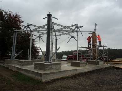
Main StructureThe assembly of the observation tower was modular; the individual modules were pre-assembled on the assembly site at the construction site. Thanks to this method, the workers operated within the height of one floor (4.5 m), minimizing the extent of work at heights. To ensure the geometric accuracy needed for connecting individual modules, a steel assembly fixture was constructed for precisely locating the steel connecting elements. Holes were drilled in the flanges of the IPE profiles, into which the steel elements were precisely inserted. As the height increased, the holes approached the center, so that the spacing of holes in the upper frame matched that of the lower frame of the next module. After the steel elements were positioned, the individual pieces were attached to the plate using screws. Holes were drilled through the plate into the thus secured element, and then a second piece was attached from the other side. The second piece was drilled through the already drilled hole to ensure the straightness of the drill. The diameter of the holes was the same as that of the bolts, which were hammered into the holes. This ensured high stiffness of the joint and minimal slip. Spring washers were placed under all nuts to prevent loosening due to oscillation and volume changes of the wood. The assembly of the module without a staircase took, on average, three days.
Staircase
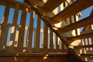
The staircase in the observation tower is made of squared timber, and the stair treads are made of larch planks.
In order to minimize work at the construction site, all pieces were prefabricated, and only installation on pre-prepared supportive elements was performed on site. After the stair flights were positioned, the balustrade panels were attached, and the installation of the staircase on one floor took about one day.
Roof
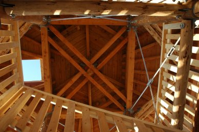
The roof has the shape of a hexagonal pyramid with two slopes. The change in slope is made at the level of the observation platform's floor. The lower part, known as the "collar," is made from interlaid larch boards and is part of the ninth module. The upper part of the roof was mounted separately and installed at the very end of the construction. It includes a canopy that covers the main observation platform. The space above the canopy remains open, and in the future, it is planned to place antennas there. Copper sheet was chosen for the roofing. A gutter was placed around the canopy to prevent unnecessary water ingress into the structure. The gutter is led to the edge of the collar, and the water is directed away from the building through downspouts.
Weather Protection
The structure is open, and all structural elements are exposed to the weather. Various methods of wood protection were considered; however, due to the installation and financial requirements from the investor, only the surface impregnation of all cuts and holes was implemented. The steel elements are hot-dip galvanized, and the other connecting elements are also protected with zinc.
The English translation is powered by AI tool. Switch to Czech to view the original text source.
1 comment
add comment
Subject
Author
Date
Ochrana dřevěné konstrukce, dotahování spojů
Přemysl Frantík Kuchař
25.11.11 10:00
show all comments
Related articles
1
11.09.2012 | Wooden constructions for living and recreation
0
07.08.2012 | Extensions on the building of Česká pojišťovna in Pankrác
1
10.07.2012 | Giant Barrel Javorník - use of glued laminated timber
0
11.06.2012 | KI Aula – non-traditional use of glued laminated timber
0
12.04.2012 | Usage of glued laminated timber in modern architecture