Extensions on the building of Česká pojišťovna in Pankrác

Publisher
Pavlína Drbálková
07.08.2012 09:30
TAROS NOVA s.r.o.
RHEINZINK ČR s.r.o.

Architect: Ing. arch. Zdeněk Hölzel
General Designer: AHK architects s.r.o., Pod radnici 2a/1235, 150 00 Prague 5
Client for wooden structures and GD of the building: Metrostav a.s., Koželužská 2246, 180 00 Prague 8
Structural design – part of the wooden structure for DSP and DPS:TAROS NOVA s.r.o., Chodská 697, 756 61 Rožnov pod Radhoštěm
Supply of wooden structures and exterior cladding, including manufacturing documentation: TAROS NOVA s.r.o.
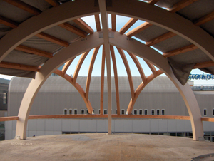
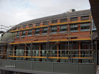
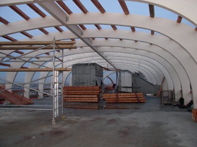
Materials-structure: glued laminated timber GL24h, timber – S10, steel S235
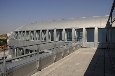
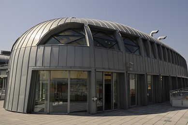
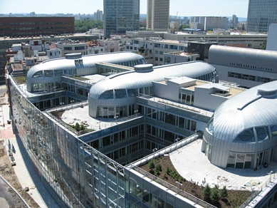
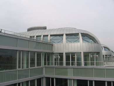
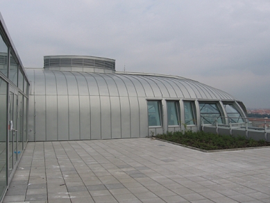
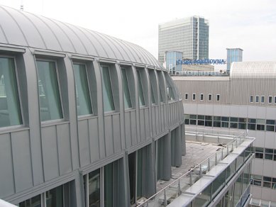
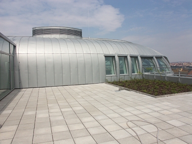
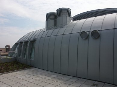
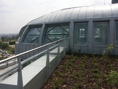
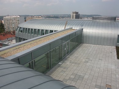
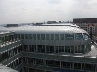
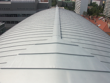
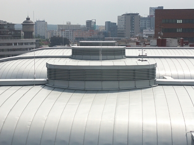
Materials – exterior cladding: titanium-zinc sheet (Rheinzink), mineral insulation, structural separation mat, safety diffusion membrane, AL vapor barrier.
Realization period: 2007-2008
Location: http://goo.gl/maps/LBiMb

Wooden Supporting Structure
The wooden structure of the extensions to the administrative complex of Česká pojišťovna, a.s. in Prague's Pankrác culminates in rounded peak-like ships. There are a total of four extensions, which have identical outlines; however, they slightly differ in terms of construction because their design must adapt to the reinforced concrete communication cores, which vary in different parts of the building.
The geometry of the structure is determined by the cross-section. The cross-section of the outer outline of the roof "rotates" along and around the longitudinal axis in the same shape, shortening and lowering at the peak. The rounding of both ends of the extension above the foci of imaginary ellipses deviates from this system - it is addressed in an atypical way. This defined geometry is a technical approximation to the originally proposed general shape by the architect.

The main supporting structure is designed as a spatial skeleton composed of transverse load-bearing frames (ribs), a connecting spinal beam at the peak, and is supplemented by 'vlašské' (Dutch) rafters that carry the roof cladding.
The ribs and beam have the same cross-section of 160 x 500 mm at the peak and always intersect at the same height level. The beam is continuous and is assembled from 4 pieces connected by means of steel connectors and bolts. The ribs are spaced approximately 2.7 m apart (variable depending on the location in the plan) and are made as three-joint frames. Individual frames are connected at the peak via a longitudinal beam using locksmith's fixtures and bolts. In the plan view, at the peak, the semi-frames meet at small angles, which slightly increase towards the ends of the ship.
Thus, the structure is self-supporting in the longitudinal direction, partially ensuring longitudinal stability. This is confirmed by transverse roof stiffeners created from rafters and diagonal steel strips.

Envelope
The final appearance of the extension buildings is determined by the execution of the roofing made of titanium-zinc sheet. Before its actual execution, it was necessary to resolve a number of atypical details, from window installation to ventilation, as well as the covering of technologies and the ventilation system outlets on the roof. Additional non-standard details appeared during the execution of the envelope frameworks, where it was necessary to mount variable height counter-battens on the segments designated by rafters, in order to create a curved surface for formwork.
The envelope composition of the extension is designed as a double-shell roof with a naturally ventilated air gap.

Upper Shell:
Total thickness approx. 230 mm
-    Titanium-zinc sheet roofing with standing seam
-    Structured separating mat
-    Board cladding 22-24mm thick
-    Counter-battens made of multiple boards stacked on top of each other and atypically cut planks – ventilated air gap 175mm thick

Lower Shell:
Total thickness approx. 335 mm
-    Safety waterproofing, diffusion foil with equivalent diffusion thickness up to 0.04m
-    Rafter 140/140   –   S10 + thermal insulation U = 0.16-0.24 W/m2K
-    Wooden framework 60/80 – S10 + thermal insulation U = 0.16-0.24 W/m2K
-    Vapor barrier with equivalent diffusion thickness of about 188m
-    The underframe grid and plasterboard ceiling were not part of the delivery from TAROS NOVA s.r.o.

Implementation
In November 2007, the installation of the load-bearing structure, safety foils, counter-battens, and formwork began. Subsequently, a safety waterproofing was applied to the formwork, which also served as a temporary covering during the winter period.
During the winter period, when it was not possible to perform roofing work, the installation of thermal insulation, internal frameworks, and vapor barriers took place.
In the spring of 2008, roofing work began (approximately 5000m2), and by mid-2008, the entire project was handed over to the client.

Author of the article: Ing. Robert Martinek, TAROS NOVA s.r.o.
The English translation is powered by AI tool. Switch to Czech to view the original text source.
0 comments
add comment

Related articles