

Architectural competition for the Center of Hall Sports - 1st place
Authors: Atelier 8000 / Ing. Martin Krupauer, Ing.arch. Jiří Střítecký
URBAN DESIGN AND BROADER RELATIONS
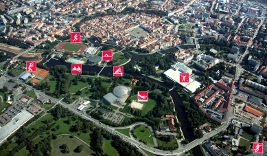
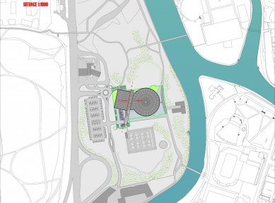
The sports hall located in Dlouhá louka is situated in a very advantageous, attractive, and traditional spot at the confluence of the Vltava and Malše rivers, in close proximity to other significant urban sports facilities (swimming stadium, ice stadium, football stadium) and primarily within walking distance of the historic city center.
The location is very well accessible by foot, by bike, by car, or via public transport.
The existing urban plan of České Budějovice in the attractive area of Dlouhá louka does not allow for significant extensive expansion of development; therefore, the existing areas designated for sports complexes by the urban plan will be utilized to the maximum possible extent.
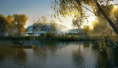
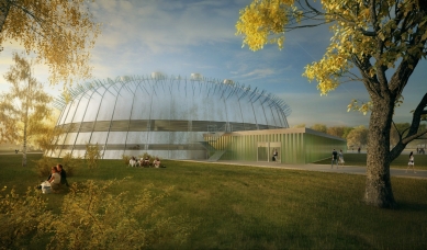
The design of the sports hall utilizes a historically established and time-tested urban concept of this locality. The green wedge of Stromovka reaching up to the historic city walls, the revitalized Sokolský island, the romantic confluence of the Vltava and Malše rivers, the nearby Háječek, and the coastal pedestrian and cycling promenades create a unique place, where the sports hall of České Budějovice is located at its core. Together with the football, ice, and swimming stadiums, it creates an exceptional sports enclave for the city and region.
The sports hall, with its variable use options, will serve as a facility for nearby schools as well as for sports that have their focus in other nearby sports facilities.
Intensified parking for cars near the hall, along with a parking lot for buses, will also be among the closest and most capacious parking lots to the historic center, with excellent access.
Already today, and especially in the future, they will become a significant "gate" for visitors to the historic center, as well as for attendees of sporting events in the nearby sports facilities and visitors and users of the administrative center of the city and region forming in the vicinity of the building of the Regional Office.
VOLUMETRIC AND ARCHITECTURAL SOLUTION
The proposed volumetric and architectural design of the building primarily draws on the morphology of sports buildings and is identified with the function of the structure.
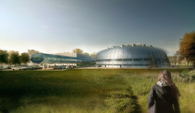
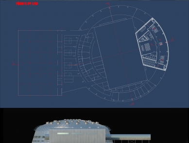
The basic principle is clear legibility of individual operations even from the outside, resulting in easy orientation for spectators and athletes. The intention is essentially a collection of buildings, namely the sports hall, training hall, athletic corridor, and facilities.
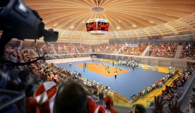
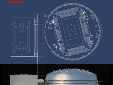
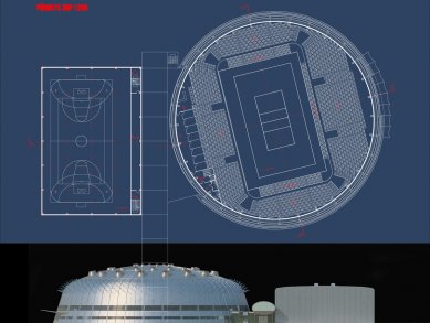
The sports hall intended for elite and competitive sport is composed of a clearly defined mass with a circular floor plan. The circular arrangement allows for placing the largest number of seats for spectators in the most attractive position, that is, close to the center of the sports facilities. The oval design of the stands creates the much-desired feeling of a "cauldron" providing maximum sporting experience for both players and spectators. The hall is "vaulted" with wooden trusses, which are the main structural and architectural motif of the entire interior.
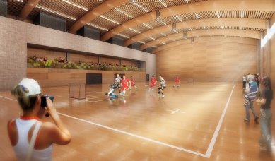
The training hall serves as a volumetric counterpoint to the sports hall. It is designed in a simple cubical shape with rounded corners, and its volume fully derives from its function. The training hall also features spectator areas that will be used primarily during tournaments.
The volumetric composition is complemented by a 90 m long running corridor, which is inserted between both halls at the level of the second floor. The tube has an elliptical cross-section and is a necessary complement to the entire project, both in terms of the overall architectural design and primarily its function.
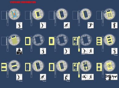
OPERATIONAL LAYOUT SOLUTION OF THE SPORTS HALL AND DESCRIPTION OF MULTIFUNCTIONAL USE
Two basic conditions, namely the creation of sufficient space for the operation of an elite volleyball team while simultaneously ensuring continuous opportunities for others to play and train, combined with demands for quality and modernity, are the fundamental starting points for the design solution.
Its principle is absolute variability of the facility allowing for preparation of both elite athletes and competitive youth athletes at any given moment while also accommodating ongoing elite sporting and social events with high spectator attendance.
The focal points of the design are the two halls, the sports hall and the training hall, intersected at the level of the second floor by the running corridor, allowing for intensive training use (more courts on one area) as well as elite and international matches not only in volleyball but also in other indoor sports. Additionally, the sports hall allows for very simple and efficient organization of social events with high attendance and quality environment.
The possibility of overlapping uses of the halls allows for strict separation of their individual functions and visitor, user, and spectator "flows."
Both athletes (elite, competitive, youth, schools) and spectators of the individual halls only move in the spaces designated for them. Conversely, all operational and technical facilities are shared and positioned in such a way as to be as efficient and usable by all operations.
Separability and structuration of spectator areas allow for maximum economy of their operation.
The object can be realized in two phases. In the first phase, the sports hall will be built with the corresponding sports, technical, and technological equipment. The second phase includes the training hall, athletic corridor, and separate technological equipment (ventilation machine room).
Sports Areas
Two sports halls form the core of the building.
sports hall - enables the organization of elite matches in all indoor sports. The variability of the front rows (telescope stands) ensures not only optimal spectator capacity but also close "contact" between spectators and players. Conversely, retracting telescopic stands will allow for maximum utilization of the playing area for training courts.
training hall - is intended for all indoor sports. Its size allows for optimal arrangement of training areas. The fixed stand ensures that this hall can also host sporting events and matches.
combination of halls - in one building offers not only the efficiency of utilizing its sports areas but also currently impossible organization of large tournaments at one site in České Budějovice. Thus, it allows a response to the current trend, particularly in youth sports (greater competitive comparison, but mainly economic efficiency and necessity).
athletic corridor - will continue to serve the preparation of athletes in winter as well as summer.
Sports Facilities
The facility offers three types of changing room facilities for athletes. Standard locker rooms for athletes correspond to the effort for variability and maximum utilization of sports areas. The home locker rooms (Volleyball Club Jihostroj České Budějovice) and the guests’ locker rooms meet the needs, trends, and requirements of contemporary elite volleyball.
Spectator Areas and Facilities
Auditorium - the width and depth of the rows allow for comfortable seating on individual seats. The retractability of the lower parts of the stands ensures maximum efficiency in the utilization of the auditorium. The technology of the telescopic stands and direct link of the chair storage to the area of the sports hall ensures high efficiency and speed in adjusting the hall for its specific use.
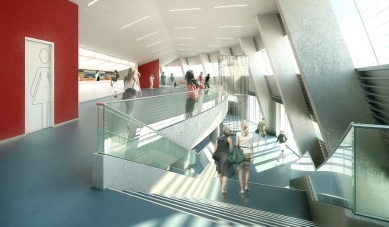
Foyer - a continuous and adequately capacious foyer located at the entrance from the river on the first floor directly connects to the spectator areas encircling the entire hall at the level of the second floor, allowing for clear, transparent, safe, and quick access to individual spectator seats and quality, commercially usable spending of spectator time outside of watching a sporting or social event (breaks, times before and after matches, refreshments, etc.). Part of the foyer will also be the Hall of Fame of the Volleyball Club Jihostroj České Budějovice. Due to variable walls, it will be possible, if needed, to "expand" the foyer area to include the Hall of Fame.
training hall - offers standard spectator seating corresponding to the sports hall. Direct access to the stand is facilitated by operational stairs through the reception.
Gastronomy - the buffet system ensures catering-style refreshments for the spectators of the sports hall.
1st Basement - media center with a direct connection to the foyer, which will serve as a capacity changing room during social events.
CONSTRUCTIONAL SOLUTION
Sports Hall
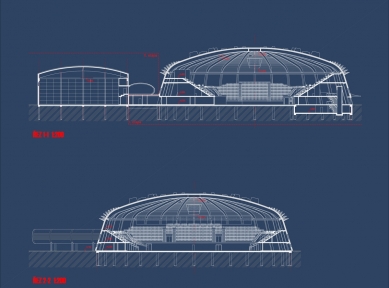
Structurally, the Sports Hall is designed as a central building with a circular floor plan. The guiding circle of the floor plan has a diameter of 68.9 m. The perimeter structures consist of prefabricated reinforced concrete columns of preliminary dimensions 900/400 mm, regularly arranged around the perimeter of the structure in segments of 11.25°, creating a thirty-two-sided polygon. The height of the columns under the truss is 11.1 m. The roofing is executed with a low dome featuring a central lantern. The load-bearing elements of the dome consist of circular wooden glued laminated trusses with variable geometry of preliminary dimensions 900-1200/240 mm, which connect to the perimeter columns. Between the trusses are placed purlins made of squared timber, and the entire dome is stabilized by steel diagonal braces executed oppositely in two mutually perpendicular axes. The trusses are linked at the location of the lantern by a ring, and at the connection points to the columns, a circumferential brace is constructed. Both rings are formed from steel elements welded from rolled profiles.
The load-bearing structures of the hall are, given the localization of the building, founded deep on drilled wide-profile piles. The floor slab is considered to have a thickness of 30-40 cm; to secure the transfer of moments from the columns to the slab and increase the stiffness of the slab-column junction (necessary to reduce horizontal deformations of the column heads), the slab is reinforced with beams running along the perimeter of the slab and in the locations of the columns. This solution will allow for maximum reduction of the pile diameter since there is no need for their collaboration with the columns in transferring horizontal loads from the wind. Another advantage is that it is not necessary to connect the head of the pile with the columns and the floor slab. A variant solution is designing a prefabricated foundation slab that will be coupled with the floor slab.
The internal structure of the stands, which connect to the perimeter columns and other internal supporting structures, consists of reinforced concrete prefabricates and is only locally supplemented by monolithic structures in places requiring atypical changes. Additionally, bracing is executed at the connection of the stands.
Perimeter and Roofing Envelope
The roof is a single-shell, unventilated, with a vapor barrier, mineral insulation, and waterproof layer for minimal roof slopes. An industrially manufactured aluminum roofing system with standing seams, Kalzip has been proposed as the roof shell.
The standing seam is designed to be watertight, preventing moisture from entering from the outside while allowing the escape of accidentally trapped moisture in the roof composition. When the material warms up, the trapped moisture transforms into water vapor. By expanding, the water vapor causes the standing seam to slightly open, allowing moisture to escape from the structure. All anchoring is hidden under the roof covering, preventing perforation of the roof shell. This allows anchoring to be conducted on anchor clips.
The continuous façade shell is interrupted only by a strip of windows at the levels of the 1st and 2nd floors. The roof is fitted with a system of light wells with a diameter of 1.5 to 2.5 m above the playing area, which shape allows for even illumination of the playing surface with daylight, while preventing glare from direct sunlight.
Above the main entrance toward the river, membranes tensioned on a steel structure are located externally, slightly set back from the façade.
Training Hall
It is designed as a single-story prefabricated reinforced concrete skeletal system, combined with wooden glued trusses with ties that capture horizontal forces. In the eastern part of the structure, three levels of facilities, stands, and technology are inserted. Glued trusses in circular shape with ties will be visibly treated as part of the interior of the building, and this fact will also correspond with features of the roof shell. The skeleton has a modulation of 7.95 x 31.8 m, a height under the tie of 9.5 m, and consists of 6 spans. Given the necessity to anchor the perimeter shell, both gables are equipped with columns at axial distances of 7.95 m. The stiffness of the structure is ensured by gable and longitudinal frames; in the longitudinal frames, a bracing wall is incorporated in the center of the building. Loads from the wind acting on the gables will be transferred to the bracing beams, which will be part of the roof. The entire structure is anticipated to have its columns anchored at the base and trusses connected with joints. The perimeter shell is expected to be lightweight, suspended on reinforced concrete columns.
The perimeter and roofing envelope have the same properties as those of the sports hall, despite being smaller in size. It is complemented by a strip of windows on the western façade.
Athletic Corridor
This new structure is inserted between the sports and training halls. It is a longitudinal oval tube, set above ground level. Structurally, it is made up of two-story transverse frames supported on isolated supports and interconnected by longitudinal beams. This creates longitudinal bracing, ensuring the stability of the structure. The internal ceiling below the running track is made as a steel-concrete construction, as well as the lower part of the tube, where the sports facilities are located. The structure is again founded on piles. The envelope is lightweight, partially glazed.
Description of Basic Equipment
Stands
On the prefabricated load-bearing structure of the stands, the tiers of the stands will be installed - prefabricated L-shaped elements, on which sports seats will be installed at the front.
Seats in the VIP stands will be based on the same principle, but with higher comfort (upholstered).
The telescopic stands will be supplied as a systematic product. The telescopic stand will consist of a steel structure. The walkable surfaces of the stands will be fitted with diamond-plate metal sheets. The extension and retraction of the telescopic stands will be manual. Similarly, the seats on these stands will be of a systematic foldable type, plastic with a foldable leg.
Illustrative diagram: plastic seats will be in a foldable version, which allows for saving space that the seat occupies in the auditorium.
with a metal structure. Seats
Seats will be fireproof and available in various colors.
TECHNICAL AND TECHNOLOGICAL EQUIPMENT
The building will be connected to existing technical infrastructure networks in a manner similar to the current sports hall.
The sports hall will be equipped with forced ventilation using compact HVAC units. The units will be equipped with filtration, heating (water heat exchangers), recovery, and possibly mixing. Gastronomic operations will be handled in designated spaces through catering.
The training hall is designated for team sports and has spectator seating for approximately 200 viewers. The purpose of the air conditioning system in this section is to ensure adequate microclimatic conditions throughout the year, with the main usage period expected to be in the winter and transitional periods.
Heating System of the Facility
The production of thermal energy is intended to cover the thermal losses of the building, to treat incoming fresh air, and to prepare hot water for use (TUV). The heat source will be a pressure-independent heat exchange station, which will be supplied from the central heating supply (CZT). The station will be located at the 1st floor level and will be dimensioned to meet the needs of both construction phases.
Supply to the facilities will be ensured from the existing connection, or possibly from a new, more capacious connection along the original route.
Ventilation
The space of the sports hall will be ventilated with a balanced system with forced air supply and exhaust. Ventilation will be provided by a supply-exhaust unit equipped with a plate heat exchanger, filters, water heaters, and evaporative coolers. Air distribution will be managed through installation shafts and technical space beneath the stands.
The training hall will be ventilated in a similar manner but with lower comfort levels. HVAC units will be located in the technological space on the 3rd floor.
In the changing rooms and facilities, a slightly negative pressure system will be arranged. The installation will ensure forced air exhaust and supply. Ventilation of the spaces will be secured by ceiling-mounted HVAC units equipped with plate heat exchangers, filters, and water heaters.
Cooling
Cooling is anticipated only for the sports hall. The main cooling source will be a condensing unit. The unit will work with environmentally friendly refrigerants and will be designed to minimize noise and vibrations that may spread throughout the building.
The cooling distribution into the hall will be conducted via the incoming fresh air using an HVAC unit equipped with a direct evaporator and through circulating ceiling units also equipped with direct evaporators. Cooling production and distribution will be managed by an automatic control system.
Plumbing
The wastewater drainage system will be gravity-fed into the existing sewer line.
Rainwater from hardened surfaces in the area of site communications and parking areas will be connected to storm drainage via oil separators.
The water supply will be connected to the existing line.
Electrical Installations
The low-voltage switchgear will be located in a separate room on the 1st floor. The main switchboard of the facility, along with additional sub-distribution boards as needed, will be placed in the switchgear.
Further assessment may anticipate the placement of a backup power source.
The sports hall located in Dlouhá louka is situated in a very advantageous, attractive, and traditional spot at the confluence of the Vltava and Malše rivers, in close proximity to other significant urban sports facilities (swimming stadium, ice stadium, football stadium) and primarily within walking distance of the historic city center.
The location is very well accessible by foot, by bike, by car, or via public transport.
The existing urban plan of České Budějovice in the attractive area of Dlouhá louka does not allow for significant extensive expansion of development; therefore, the existing areas designated for sports complexes by the urban plan will be utilized to the maximum possible extent.
The design of the sports hall utilizes a historically established and time-tested urban concept of this locality. The green wedge of Stromovka reaching up to the historic city walls, the revitalized Sokolský island, the romantic confluence of the Vltava and Malše rivers, the nearby Háječek, and the coastal pedestrian and cycling promenades create a unique place, where the sports hall of České Budějovice is located at its core. Together with the football, ice, and swimming stadiums, it creates an exceptional sports enclave for the city and region.
The sports hall, with its variable use options, will serve as a facility for nearby schools as well as for sports that have their focus in other nearby sports facilities.
Intensified parking for cars near the hall, along with a parking lot for buses, will also be among the closest and most capacious parking lots to the historic center, with excellent access.
Already today, and especially in the future, they will become a significant "gate" for visitors to the historic center, as well as for attendees of sporting events in the nearby sports facilities and visitors and users of the administrative center of the city and region forming in the vicinity of the building of the Regional Office.
VOLUMETRIC AND ARCHITECTURAL SOLUTION
The proposed volumetric and architectural design of the building primarily draws on the morphology of sports buildings and is identified with the function of the structure.
The basic principle is clear legibility of individual operations even from the outside, resulting in easy orientation for spectators and athletes. The intention is essentially a collection of buildings, namely the sports hall, training hall, athletic corridor, and facilities.
The sports hall intended for elite and competitive sport is composed of a clearly defined mass with a circular floor plan. The circular arrangement allows for placing the largest number of seats for spectators in the most attractive position, that is, close to the center of the sports facilities. The oval design of the stands creates the much-desired feeling of a "cauldron" providing maximum sporting experience for both players and spectators. The hall is "vaulted" with wooden trusses, which are the main structural and architectural motif of the entire interior.
The training hall serves as a volumetric counterpoint to the sports hall. It is designed in a simple cubical shape with rounded corners, and its volume fully derives from its function. The training hall also features spectator areas that will be used primarily during tournaments.
The volumetric composition is complemented by a 90 m long running corridor, which is inserted between both halls at the level of the second floor. The tube has an elliptical cross-section and is a necessary complement to the entire project, both in terms of the overall architectural design and primarily its function.
OPERATIONAL LAYOUT SOLUTION OF THE SPORTS HALL AND DESCRIPTION OF MULTIFUNCTIONAL USE
Two basic conditions, namely the creation of sufficient space for the operation of an elite volleyball team while simultaneously ensuring continuous opportunities for others to play and train, combined with demands for quality and modernity, are the fundamental starting points for the design solution.
Its principle is absolute variability of the facility allowing for preparation of both elite athletes and competitive youth athletes at any given moment while also accommodating ongoing elite sporting and social events with high spectator attendance.
The focal points of the design are the two halls, the sports hall and the training hall, intersected at the level of the second floor by the running corridor, allowing for intensive training use (more courts on one area) as well as elite and international matches not only in volleyball but also in other indoor sports. Additionally, the sports hall allows for very simple and efficient organization of social events with high attendance and quality environment.
The possibility of overlapping uses of the halls allows for strict separation of their individual functions and visitor, user, and spectator "flows."
Both athletes (elite, competitive, youth, schools) and spectators of the individual halls only move in the spaces designated for them. Conversely, all operational and technical facilities are shared and positioned in such a way as to be as efficient and usable by all operations.
Separability and structuration of spectator areas allow for maximum economy of their operation.
The object can be realized in two phases. In the first phase, the sports hall will be built with the corresponding sports, technical, and technological equipment. The second phase includes the training hall, athletic corridor, and separate technological equipment (ventilation machine room).
Sports Areas
Two sports halls form the core of the building.
sports hall - enables the organization of elite matches in all indoor sports. The variability of the front rows (telescope stands) ensures not only optimal spectator capacity but also close "contact" between spectators and players. Conversely, retracting telescopic stands will allow for maximum utilization of the playing area for training courts.
training hall - is intended for all indoor sports. Its size allows for optimal arrangement of training areas. The fixed stand ensures that this hall can also host sporting events and matches.
combination of halls - in one building offers not only the efficiency of utilizing its sports areas but also currently impossible organization of large tournaments at one site in České Budějovice. Thus, it allows a response to the current trend, particularly in youth sports (greater competitive comparison, but mainly economic efficiency and necessity).
athletic corridor - will continue to serve the preparation of athletes in winter as well as summer.
Sports Facilities
The facility offers three types of changing room facilities for athletes. Standard locker rooms for athletes correspond to the effort for variability and maximum utilization of sports areas. The home locker rooms (Volleyball Club Jihostroj České Budějovice) and the guests’ locker rooms meet the needs, trends, and requirements of contemporary elite volleyball.
Spectator Areas and Facilities
Auditorium - the width and depth of the rows allow for comfortable seating on individual seats. The retractability of the lower parts of the stands ensures maximum efficiency in the utilization of the auditorium. The technology of the telescopic stands and direct link of the chair storage to the area of the sports hall ensures high efficiency and speed in adjusting the hall for its specific use.
Foyer - a continuous and adequately capacious foyer located at the entrance from the river on the first floor directly connects to the spectator areas encircling the entire hall at the level of the second floor, allowing for clear, transparent, safe, and quick access to individual spectator seats and quality, commercially usable spending of spectator time outside of watching a sporting or social event (breaks, times before and after matches, refreshments, etc.). Part of the foyer will also be the Hall of Fame of the Volleyball Club Jihostroj České Budějovice. Due to variable walls, it will be possible, if needed, to "expand" the foyer area to include the Hall of Fame.
training hall - offers standard spectator seating corresponding to the sports hall. Direct access to the stand is facilitated by operational stairs through the reception.
Gastronomy - the buffet system ensures catering-style refreshments for the spectators of the sports hall.
1st Basement - media center with a direct connection to the foyer, which will serve as a capacity changing room during social events.
CONSTRUCTIONAL SOLUTION
Sports Hall
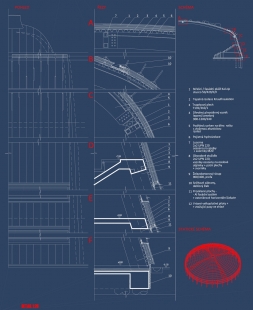
Structurally, the Sports Hall is designed as a central building with a circular floor plan. The guiding circle of the floor plan has a diameter of 68.9 m. The perimeter structures consist of prefabricated reinforced concrete columns of preliminary dimensions 900/400 mm, regularly arranged around the perimeter of the structure in segments of 11.25°, creating a thirty-two-sided polygon. The height of the columns under the truss is 11.1 m. The roofing is executed with a low dome featuring a central lantern. The load-bearing elements of the dome consist of circular wooden glued laminated trusses with variable geometry of preliminary dimensions 900-1200/240 mm, which connect to the perimeter columns. Between the trusses are placed purlins made of squared timber, and the entire dome is stabilized by steel diagonal braces executed oppositely in two mutually perpendicular axes. The trusses are linked at the location of the lantern by a ring, and at the connection points to the columns, a circumferential brace is constructed. Both rings are formed from steel elements welded from rolled profiles.
The load-bearing structures of the hall are, given the localization of the building, founded deep on drilled wide-profile piles. The floor slab is considered to have a thickness of 30-40 cm; to secure the transfer of moments from the columns to the slab and increase the stiffness of the slab-column junction (necessary to reduce horizontal deformations of the column heads), the slab is reinforced with beams running along the perimeter of the slab and in the locations of the columns. This solution will allow for maximum reduction of the pile diameter since there is no need for their collaboration with the columns in transferring horizontal loads from the wind. Another advantage is that it is not necessary to connect the head of the pile with the columns and the floor slab. A variant solution is designing a prefabricated foundation slab that will be coupled with the floor slab.
The internal structure of the stands, which connect to the perimeter columns and other internal supporting structures, consists of reinforced concrete prefabricates and is only locally supplemented by monolithic structures in places requiring atypical changes. Additionally, bracing is executed at the connection of the stands.
Perimeter and Roofing Envelope
The roof is a single-shell, unventilated, with a vapor barrier, mineral insulation, and waterproof layer for minimal roof slopes. An industrially manufactured aluminum roofing system with standing seams, Kalzip has been proposed as the roof shell.
The standing seam is designed to be watertight, preventing moisture from entering from the outside while allowing the escape of accidentally trapped moisture in the roof composition. When the material warms up, the trapped moisture transforms into water vapor. By expanding, the water vapor causes the standing seam to slightly open, allowing moisture to escape from the structure. All anchoring is hidden under the roof covering, preventing perforation of the roof shell. This allows anchoring to be conducted on anchor clips.
The continuous façade shell is interrupted only by a strip of windows at the levels of the 1st and 2nd floors. The roof is fitted with a system of light wells with a diameter of 1.5 to 2.5 m above the playing area, which shape allows for even illumination of the playing surface with daylight, while preventing glare from direct sunlight.
Above the main entrance toward the river, membranes tensioned on a steel structure are located externally, slightly set back from the façade.
Training Hall
It is designed as a single-story prefabricated reinforced concrete skeletal system, combined with wooden glued trusses with ties that capture horizontal forces. In the eastern part of the structure, three levels of facilities, stands, and technology are inserted. Glued trusses in circular shape with ties will be visibly treated as part of the interior of the building, and this fact will also correspond with features of the roof shell. The skeleton has a modulation of 7.95 x 31.8 m, a height under the tie of 9.5 m, and consists of 6 spans. Given the necessity to anchor the perimeter shell, both gables are equipped with columns at axial distances of 7.95 m. The stiffness of the structure is ensured by gable and longitudinal frames; in the longitudinal frames, a bracing wall is incorporated in the center of the building. Loads from the wind acting on the gables will be transferred to the bracing beams, which will be part of the roof. The entire structure is anticipated to have its columns anchored at the base and trusses connected with joints. The perimeter shell is expected to be lightweight, suspended on reinforced concrete columns.
The perimeter and roofing envelope have the same properties as those of the sports hall, despite being smaller in size. It is complemented by a strip of windows on the western façade.
Athletic Corridor
This new structure is inserted between the sports and training halls. It is a longitudinal oval tube, set above ground level. Structurally, it is made up of two-story transverse frames supported on isolated supports and interconnected by longitudinal beams. This creates longitudinal bracing, ensuring the stability of the structure. The internal ceiling below the running track is made as a steel-concrete construction, as well as the lower part of the tube, where the sports facilities are located. The structure is again founded on piles. The envelope is lightweight, partially glazed.
Description of Basic Equipment
Stands
On the prefabricated load-bearing structure of the stands, the tiers of the stands will be installed - prefabricated L-shaped elements, on which sports seats will be installed at the front.
Seats in the VIP stands will be based on the same principle, but with higher comfort (upholstered).
The telescopic stands will be supplied as a systematic product. The telescopic stand will consist of a steel structure. The walkable surfaces of the stands will be fitted with diamond-plate metal sheets. The extension and retraction of the telescopic stands will be manual. Similarly, the seats on these stands will be of a systematic foldable type, plastic with a foldable leg.
Illustrative diagram: plastic seats will be in a foldable version, which allows for saving space that the seat occupies in the auditorium.
with a metal structure. Seats
Seats will be fireproof and available in various colors.
TECHNICAL AND TECHNOLOGICAL EQUIPMENT
The building will be connected to existing technical infrastructure networks in a manner similar to the current sports hall.
The sports hall will be equipped with forced ventilation using compact HVAC units. The units will be equipped with filtration, heating (water heat exchangers), recovery, and possibly mixing. Gastronomic operations will be handled in designated spaces through catering.
The training hall is designated for team sports and has spectator seating for approximately 200 viewers. The purpose of the air conditioning system in this section is to ensure adequate microclimatic conditions throughout the year, with the main usage period expected to be in the winter and transitional periods.
Heating System of the Facility
The production of thermal energy is intended to cover the thermal losses of the building, to treat incoming fresh air, and to prepare hot water for use (TUV). The heat source will be a pressure-independent heat exchange station, which will be supplied from the central heating supply (CZT). The station will be located at the 1st floor level and will be dimensioned to meet the needs of both construction phases.
Supply to the facilities will be ensured from the existing connection, or possibly from a new, more capacious connection along the original route.
Ventilation
The space of the sports hall will be ventilated with a balanced system with forced air supply and exhaust. Ventilation will be provided by a supply-exhaust unit equipped with a plate heat exchanger, filters, water heaters, and evaporative coolers. Air distribution will be managed through installation shafts and technical space beneath the stands.
The training hall will be ventilated in a similar manner but with lower comfort levels. HVAC units will be located in the technological space on the 3rd floor.
In the changing rooms and facilities, a slightly negative pressure system will be arranged. The installation will ensure forced air exhaust and supply. Ventilation of the spaces will be secured by ceiling-mounted HVAC units equipped with plate heat exchangers, filters, and water heaters.
Cooling
Cooling is anticipated only for the sports hall. The main cooling source will be a condensing unit. The unit will work with environmentally friendly refrigerants and will be designed to minimize noise and vibrations that may spread throughout the building.
The cooling distribution into the hall will be conducted via the incoming fresh air using an HVAC unit equipped with a direct evaporator and through circulating ceiling units also equipped with direct evaporators. Cooling production and distribution will be managed by an automatic control system.
Plumbing
The wastewater drainage system will be gravity-fed into the existing sewer line.
Rainwater from hardened surfaces in the area of site communications and parking areas will be connected to storm drainage via oil separators.
The water supply will be connected to the existing line.
Electrical Installations
The low-voltage switchgear will be located in a separate room on the 1st floor. The main switchboard of the facility, along with additional sub-distribution boards as needed, will be placed in the switchgear.
Further assessment may anticipate the placement of a backup power source.
The English translation is powered by AI tool. Switch to Czech to view the original text source.

0 comments
add comment
Related articles
0
03.03.2023 | České Budějovice will have a new sports and leisure area by the river with a beach
0
19.03.2018 | Some citizens of Č. Budějovice disagree with the demolition of the sports hall
0
15.05.2017 | The construction of the hall in České Budějovice could start next year
8
25.02.2013 | Center for Indoor Sports in České Budějovice - competition results
0
25.02.2013 | Architectural competition for the Sports Hall Center - 2nd place
0
25.02.2013 | Architectural Competition for the Indoor Sports Center - 3rd Place
0
25.02.2013 | Architectural competition for the Indoor Sports Center - 4th place