
Komenský Bridge in Jaroměř

Address:
Dr. E. Beneše,
Jaroměř,
Czech Republic
Investor:Město Jaroměř
Contest:2013
Completion:2013-15
Price:22 500 000 CZK
Literatura

INTRO
05 - Kov
VEGA s.r.o., 2018189 Kč
Cooperation:
Excon a. s. - Miloslav Lukeš, Jindřich Beran
Mott MacDonald CZ - Petr Nehasil
Meridin - Pavel Friedberger
Main Contractors:
Jaroměř Company (Chládek a Tintěra, Eurovia Cs)
OK – BE
Tesion Systems
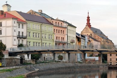
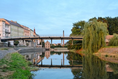
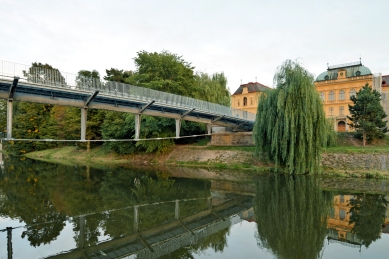
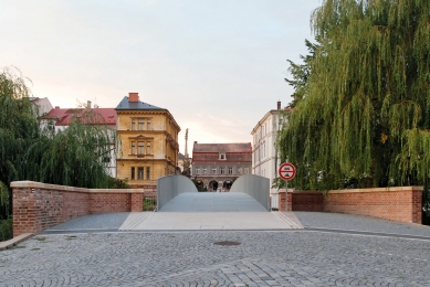
The original Komenského Bridge from 1886 connected the historic city center with the then newly organized urban space called Na Ostrově. It was a link between two urban areas that were very different in planning and architecture, formed by a lattice steel structure with two different spans and varying construction heights. Although it was a skewed bridge, its design was executed as a straight structure, with only the outer structural span exhibiting atypical features for skewed support on the embankment piers and on the equally skewed intermediate support. Due to the varying heights of the embankment piers, the bridge was set at a slight incline. Despite being a simple, pragmatic construction with relatively low architectural ambitions, the original Komenského Bridge became, until its demise in June 2013, not only a busy urban communication route but also integrated seamlessly into the city panorama due to its slender construction. The restoration of this historically evolved situation within the limiting conditions of investment costs posed a challenge, requiring not only technical ingenuity but also a certain architectural restraint and the will to avoid both exaggerated modernist gestures and retrospectively nostalgic reminiscences.
Alongside relatively low investment costs, it was primarily the demand to preserve the historical embankment piers that became a fundamental criterion limiting the choice of load-bearing structure to static systems operating longitudinally on the supports like a simple beam. The authors excluded systems with a supporting arch, which met this criterion in view of the urban panorama, thereby limiting the choice of load-bearing structure to beam systems.
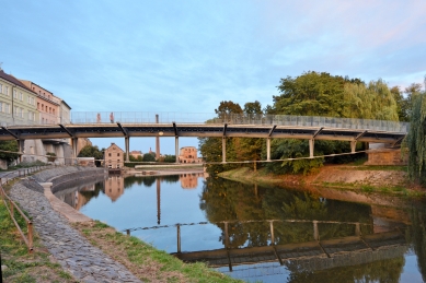
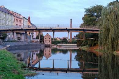
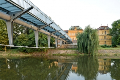
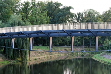
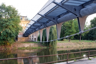
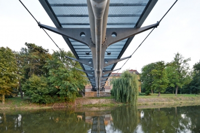
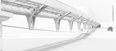
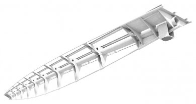
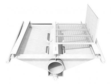
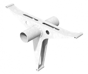
The requirement for a network collector led the authors to the idea of transforming this mostly secondary element into a central motif of the load-bearing beam structure. They used it as a central compression member, stabilized by three pre-tensioned rods. The lower rod, shaped like a segment of a circle, runs in a vertical plane and, along with the rise of the central tube, transmits vertical forces, while the two upper rods, in the shape of spatial curves with a footprint of circular arcs, not only transmit vertical loading effects but also stabilize the system in the transverse direction and provide it with torsional rigidity. To transfer forces from the tension system to the central compression member, in addition to two diagonally stiffened end spans, eight Y-shaped crossbars supported three longitudinal beams carrying a grating deck. By consistently localizing pressure to the center of the structure and tension components to its periphery, a tensioned beam was created that combines spatial rigidity with low weight and thus low material consumption. The load-bearing structure thus consists of a spatially rigid triangular prism with a clear division into components stressed by compression and those stressed by tension (bending in the central tube and in the vertical crossbars, of course, exists, but is not significant for the chosen type of construction). Conceptually, it represents a system related to tensegrity structures, as it employs one of their principles, i.e., pre-tensioning of the tension elements by a force that ensures tensile stresses in all loading states.
The structure is supported on two pot bearings (one of which is horizontally movable) at the end points of the central compression member. It is stabilized against overturning by adjustable pre-tensioned rods. This method of foundation allows for maintaining a statically and manufacturing advantageous direct construction regardless of its placement in skewed embankment piers. Both embankment piers have been preserved and modified for the new situation with pockets containing a closing wall and a supporting concrete threshold.
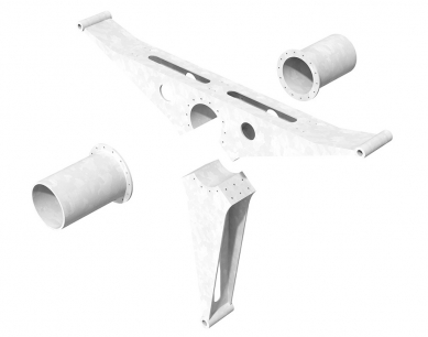
The central compression member (and also the network collector) is a tube Ø 762 x 16 mm, describing a circular arc with a rise of 1050 mm. The end spans are made up of welded constructions with diagonal reinforcements from tubes Ø168 x 10 mm, transmitting tension from three tension rods to the central compression member. The compression system is further complemented by three HEA 240 profiles, which support the grating deck.
The tension system consists of three rods (1 x Ø 102 mm + 2 x Ø 52 mm), whose components are fitted with opposite threads at their ends and screwed into threaded connectors at an appropriate angle that correspond to the curve's bend, anchored to sleeves at the ends of the crossarms. The tension system ends in threaded nuts resting on the welds of both end spans. Pre-tensioning was introduced into the tension system hydraulically, via tensioning nuts located at the midpoint of each tension component.
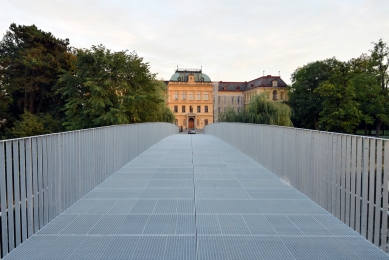
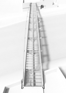
The surface of the deck consists of 164 welded grating sections measuring 2250 x 750 mm with a standard division of 33.3 x 11.1 mm. The load-bearing strips have a cross-section of 45 x 3 mm and the spacer strips 10 x 3 mm. The edges of the strips are fitted with anti-slip serration. The railing, with a total height of 1350 mm, consists of vertical profiles with a cross-section of 60 x 5 mm at an axial spacing of 105 mm. The upper edge is lined with a profile of the same cross-section, while the lower edge, resting on the top flange of HEA 240, is welded to a side edging strip of the adjacent grating. The deck is intended for pedestrians, cyclists, and maintenance vehicles with a weight limit of 3.5 t.
All parts of the load-bearing and non-load-bearing steel structure are hot-dip galvanized. The load-bearing structure was assembled on the shore on provisional supports, where it was also pre-tensioned. It was then set in place by a crane onto the prepared bearings of the embankment piers.
The public lighting consists of 36 LED spotlights angled from below at the grating deck.
Basic Data
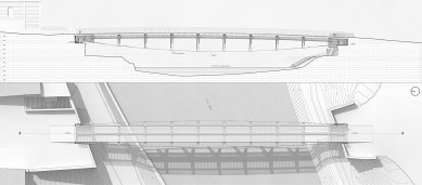
The new bridge serves to transfer pedestrian and cycling traffic with allowed vehicle access of 3.5 t. The length of the bridge is 61.5 m, and the span (distance between supports) is 59.5 m. On the left bank, the elevation is 900 mm higher than on the right bank. The deck is horizontal in cross-section. The clear width between the railings is 4.5 m. The structural height of the bridge (distance between the lower and upper tension rods) at the mid-span is 4650 mm. The bridge also facilitates the passage of a water pipeline, street lighting distribution, and high voltage conduits. Conceptually and architecturally, the bridge relates to the planned revitalization of the square, including the restoration of stormwater drainage. The resulting slopes of the deck and the surface of the abutments comply with regulations for the movement of persons with limited mobility and orientation.
Conceptual and Dispositional Design of the Bridge
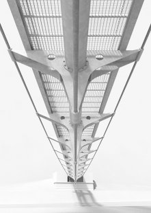
Given the requirement to preserve the historical embankment piers, the bridge was installed as a simple beam on them. The sufficient height of the elevation of the transferred communication above the level of a hundred-year flood allowed the design of a spatially pre-tensioned tensioned construction. The backbone tubular structure with three pre-tensioned rods, through which horizontal and vertical loads are transmitted via three-sided cross members, has a cross-section in the shape of an isosceles triangle. The forces generated in the rods from their pre-tensioning and from the load on the bridge are transmitted at both ends of the bridge through end welds into the backbone structure and partially into the three longitudinal HEA 240 beams, on which the grating deck is supported. The backbone structure, with dimensions of 762x16 mm, has a vertical rise of the circular arc part of 1050 mm. The three-sided crossbars of I or U profile at the top, with variable web width at an axial spacing of 600 mm, are arranged such that the axes of the lower tips are perpendicular to the circle of the backbone tube and converge at a single point.
The lower rod, made up of M105 threaded bars, has an arc shape, while the upper or lateral rods, M56 threaded bars, have the shape of spatial curves. The rods are interrupted between the cross members by tensioning nuts for introducing pre-tensioning. The connectors of the rods at the curve's bend, which are hinged in sleeves at the ends of the cross members, have threads cut at an angle corresponding to the bend of the curve. Compared to the standard detail of tensioned members at the bend with end fittings on both sides, this innovation significantly reduced costs and visually calmed these structures. The hinged connection of the connector eliminates inaccuracies in the resulting geometry of the structure and allows the construction to respond naturally to minor changes in geometry under load.
At the ends of the bridge, the rods are anchored through end nuts to spatial welds. The lower rod is guided through a tubular sleeve within the backbone tube such that the anchoring through the end nut is positioned along its axis. The upper (lateral) rods are anchored in the cross members of the weldment. The grating deck is divided in cross-section into two parts, to which strip railings are welded on the sides. The strips of the deck create openings of 30x10mm and have an anti-slip treatment on the upper surface. The yield strength of the load-bearing construction material is 355 MPa, for the rods 460 (upper) or 520 MPa (lower), and for the grates and auxiliary constructions 235 MPa. On the right bank, the bridge is supported on a fixed pot bearing, and on the left bank, on a movable pot bearing. Transverse stability is ensured on both sides by two vertical adjustable pre-tensioned rods.
Both embankment piers have been preserved. The completely retained lower parts have been reinforced. The upper parts of the piers were dismantled due to their degraded condition, rebuilt, and equipped with new closing walls and supporting thresholds. The reconstruction of the piers also included water pipeline shafts, drainage into the new stormwater drainage system, and the reconstruction of surfaces and slopes of the bridge's abutments.
Manufacturing, Assembly, and Pre-tensioning
The chosen geometry of the bridge allowed for the unification of parts. All parts of the central pressure tube with flanges are the same, as are the longitudinal beams and floor gratings with railings. This significantly simplified the production documentation and clarified the manufacturing process. All parts of the load-bearing and non-load-bearing steel structure were dimensioned and detailed for surface protection through hot-dip galvanizing without additional surface treatment. The load-bearing structure was pre-assembled prior to galvanizing in the workshop. On site, the structure was assembled on the shore on provisional supports, where it was also pre-tensioned. Pre-tensioning of the rods achieved several goals: In addition to the rise of the structure compensating the deflection from permanent and approximately 1/3 of live load, the upper rods were pre-tensioned to values that ensure their tensile stress under each load combination. Thus, regarding pre-tensioning, there was no need to raise the bridge during production. By introducing pre-tensioning, a favorable redistribution of internal forces was achieved, especially bending moments in the central tube and in the cross members with opposite orientation to bending moments from permanent and useful load. The main part of the pre-tensioning was introduced even before the activation of the longitudinal beams, which statically cooperate only for the live load, thus allowing them to be designed to be slender.
Pre-tensioning was measured tensometrically in a full bridge configuration and hydraulically. The pre-tensioning procedure was mathematically optimized using interaction matrices and linear programming. The resulting values of pre-tensioning and deformation matched the projected values very well. After activation with pre-tensioning, the structure was set in place by a crane onto the prepared bearings of the embankment piers. Finally, the deck was installed with railings, and vertical stabilizing rods were pre-tensioned. Two insulated water pipes and four high voltage conduits were inserted into the backbone tube already on the shore. The reliability and usability of the structure were demonstrated through static and dynamic tests. Dampers of oscillations were not necessary to install.
In Conclusion
The chosen structural solution of the bridge has been used for the first time in our country. In Europe, according to known sources, a similar approach has only been taken for the footbridge in Ortisei, Italy, where, however, the central compression element is absent, and the forces from the three pre-tensioned cables are transmitted to the embankment supports. In designing the bridge in Jaroměř, original details and assembly and pre-tensioning procedures were developed, which will surely inspire further implementations of pre-tensioned tensioned structures. The projects for the territorial decision, building permit, and implementation were prepared within 80 days, including discussions. The construction, including the development of manufacturing documentation and the production of the structure, predominantly took place in winter, lasting 170 days. The actual pre-assembly of the bridge on the prepared supports, including pre-tensioning, took 14 days, with the deck being mounted onto the structure already settled on the bearings. The load-bearing structure was manufactured to a high standard, and during galvanizing, the suitability of the chosen details was confirmed.
Excon a. s. - Miloslav Lukeš, Jindřich Beran
Mott MacDonald CZ - Petr Nehasil
Meridin - Pavel Friedberger
Main Contractors:
Jaroměř Company (Chládek a Tintěra, Eurovia Cs)
OK – BE
Tesion Systems
The original Komenského Bridge from 1886 connected the historic city center with the then newly organized urban space called Na Ostrově. It was a link between two urban areas that were very different in planning and architecture, formed by a lattice steel structure with two different spans and varying construction heights. Although it was a skewed bridge, its design was executed as a straight structure, with only the outer structural span exhibiting atypical features for skewed support on the embankment piers and on the equally skewed intermediate support. Due to the varying heights of the embankment piers, the bridge was set at a slight incline. Despite being a simple, pragmatic construction with relatively low architectural ambitions, the original Komenského Bridge became, until its demise in June 2013, not only a busy urban communication route but also integrated seamlessly into the city panorama due to its slender construction. The restoration of this historically evolved situation within the limiting conditions of investment costs posed a challenge, requiring not only technical ingenuity but also a certain architectural restraint and the will to avoid both exaggerated modernist gestures and retrospectively nostalgic reminiscences.
Alongside relatively low investment costs, it was primarily the demand to preserve the historical embankment piers that became a fundamental criterion limiting the choice of load-bearing structure to static systems operating longitudinally on the supports like a simple beam. The authors excluded systems with a supporting arch, which met this criterion in view of the urban panorama, thereby limiting the choice of load-bearing structure to beam systems.
The requirement for a network collector led the authors to the idea of transforming this mostly secondary element into a central motif of the load-bearing beam structure. They used it as a central compression member, stabilized by three pre-tensioned rods. The lower rod, shaped like a segment of a circle, runs in a vertical plane and, along with the rise of the central tube, transmits vertical forces, while the two upper rods, in the shape of spatial curves with a footprint of circular arcs, not only transmit vertical loading effects but also stabilize the system in the transverse direction and provide it with torsional rigidity. To transfer forces from the tension system to the central compression member, in addition to two diagonally stiffened end spans, eight Y-shaped crossbars supported three longitudinal beams carrying a grating deck. By consistently localizing pressure to the center of the structure and tension components to its periphery, a tensioned beam was created that combines spatial rigidity with low weight and thus low material consumption. The load-bearing structure thus consists of a spatially rigid triangular prism with a clear division into components stressed by compression and those stressed by tension (bending in the central tube and in the vertical crossbars, of course, exists, but is not significant for the chosen type of construction). Conceptually, it represents a system related to tensegrity structures, as it employs one of their principles, i.e., pre-tensioning of the tension elements by a force that ensures tensile stresses in all loading states.
The structure is supported on two pot bearings (one of which is horizontally movable) at the end points of the central compression member. It is stabilized against overturning by adjustable pre-tensioned rods. This method of foundation allows for maintaining a statically and manufacturing advantageous direct construction regardless of its placement in skewed embankment piers. Both embankment piers have been preserved and modified for the new situation with pockets containing a closing wall and a supporting concrete threshold.
The central compression member (and also the network collector) is a tube Ø 762 x 16 mm, describing a circular arc with a rise of 1050 mm. The end spans are made up of welded constructions with diagonal reinforcements from tubes Ø168 x 10 mm, transmitting tension from three tension rods to the central compression member. The compression system is further complemented by three HEA 240 profiles, which support the grating deck.
The tension system consists of three rods (1 x Ø 102 mm + 2 x Ø 52 mm), whose components are fitted with opposite threads at their ends and screwed into threaded connectors at an appropriate angle that correspond to the curve's bend, anchored to sleeves at the ends of the crossarms. The tension system ends in threaded nuts resting on the welds of both end spans. Pre-tensioning was introduced into the tension system hydraulically, via tensioning nuts located at the midpoint of each tension component.
The surface of the deck consists of 164 welded grating sections measuring 2250 x 750 mm with a standard division of 33.3 x 11.1 mm. The load-bearing strips have a cross-section of 45 x 3 mm and the spacer strips 10 x 3 mm. The edges of the strips are fitted with anti-slip serration. The railing, with a total height of 1350 mm, consists of vertical profiles with a cross-section of 60 x 5 mm at an axial spacing of 105 mm. The upper edge is lined with a profile of the same cross-section, while the lower edge, resting on the top flange of HEA 240, is welded to a side edging strip of the adjacent grating. The deck is intended for pedestrians, cyclists, and maintenance vehicles with a weight limit of 3.5 t.
All parts of the load-bearing and non-load-bearing steel structure are hot-dip galvanized. The load-bearing structure was assembled on the shore on provisional supports, where it was also pre-tensioned. It was then set in place by a crane onto the prepared bearings of the embankment piers.
The public lighting consists of 36 LED spotlights angled from below at the grating deck.
Basic Data
The new bridge serves to transfer pedestrian and cycling traffic with allowed vehicle access of 3.5 t. The length of the bridge is 61.5 m, and the span (distance between supports) is 59.5 m. On the left bank, the elevation is 900 mm higher than on the right bank. The deck is horizontal in cross-section. The clear width between the railings is 4.5 m. The structural height of the bridge (distance between the lower and upper tension rods) at the mid-span is 4650 mm. The bridge also facilitates the passage of a water pipeline, street lighting distribution, and high voltage conduits. Conceptually and architecturally, the bridge relates to the planned revitalization of the square, including the restoration of stormwater drainage. The resulting slopes of the deck and the surface of the abutments comply with regulations for the movement of persons with limited mobility and orientation.
Conceptual and Dispositional Design of the Bridge
Given the requirement to preserve the historical embankment piers, the bridge was installed as a simple beam on them. The sufficient height of the elevation of the transferred communication above the level of a hundred-year flood allowed the design of a spatially pre-tensioned tensioned construction. The backbone tubular structure with three pre-tensioned rods, through which horizontal and vertical loads are transmitted via three-sided cross members, has a cross-section in the shape of an isosceles triangle. The forces generated in the rods from their pre-tensioning and from the load on the bridge are transmitted at both ends of the bridge through end welds into the backbone structure and partially into the three longitudinal HEA 240 beams, on which the grating deck is supported. The backbone structure, with dimensions of 762x16 mm, has a vertical rise of the circular arc part of 1050 mm. The three-sided crossbars of I or U profile at the top, with variable web width at an axial spacing of 600 mm, are arranged such that the axes of the lower tips are perpendicular to the circle of the backbone tube and converge at a single point.
The lower rod, made up of M105 threaded bars, has an arc shape, while the upper or lateral rods, M56 threaded bars, have the shape of spatial curves. The rods are interrupted between the cross members by tensioning nuts for introducing pre-tensioning. The connectors of the rods at the curve's bend, which are hinged in sleeves at the ends of the cross members, have threads cut at an angle corresponding to the bend of the curve. Compared to the standard detail of tensioned members at the bend with end fittings on both sides, this innovation significantly reduced costs and visually calmed these structures. The hinged connection of the connector eliminates inaccuracies in the resulting geometry of the structure and allows the construction to respond naturally to minor changes in geometry under load.
At the ends of the bridge, the rods are anchored through end nuts to spatial welds. The lower rod is guided through a tubular sleeve within the backbone tube such that the anchoring through the end nut is positioned along its axis. The upper (lateral) rods are anchored in the cross members of the weldment. The grating deck is divided in cross-section into two parts, to which strip railings are welded on the sides. The strips of the deck create openings of 30x10mm and have an anti-slip treatment on the upper surface. The yield strength of the load-bearing construction material is 355 MPa, for the rods 460 (upper) or 520 MPa (lower), and for the grates and auxiliary constructions 235 MPa. On the right bank, the bridge is supported on a fixed pot bearing, and on the left bank, on a movable pot bearing. Transverse stability is ensured on both sides by two vertical adjustable pre-tensioned rods.
Both embankment piers have been preserved. The completely retained lower parts have been reinforced. The upper parts of the piers were dismantled due to their degraded condition, rebuilt, and equipped with new closing walls and supporting thresholds. The reconstruction of the piers also included water pipeline shafts, drainage into the new stormwater drainage system, and the reconstruction of surfaces and slopes of the bridge's abutments.
Manufacturing, Assembly, and Pre-tensioning
The chosen geometry of the bridge allowed for the unification of parts. All parts of the central pressure tube with flanges are the same, as are the longitudinal beams and floor gratings with railings. This significantly simplified the production documentation and clarified the manufacturing process. All parts of the load-bearing and non-load-bearing steel structure were dimensioned and detailed for surface protection through hot-dip galvanizing without additional surface treatment. The load-bearing structure was pre-assembled prior to galvanizing in the workshop. On site, the structure was assembled on the shore on provisional supports, where it was also pre-tensioned. Pre-tensioning of the rods achieved several goals: In addition to the rise of the structure compensating the deflection from permanent and approximately 1/3 of live load, the upper rods were pre-tensioned to values that ensure their tensile stress under each load combination. Thus, regarding pre-tensioning, there was no need to raise the bridge during production. By introducing pre-tensioning, a favorable redistribution of internal forces was achieved, especially bending moments in the central tube and in the cross members with opposite orientation to bending moments from permanent and useful load. The main part of the pre-tensioning was introduced even before the activation of the longitudinal beams, which statically cooperate only for the live load, thus allowing them to be designed to be slender.
Pre-tensioning was measured tensometrically in a full bridge configuration and hydraulically. The pre-tensioning procedure was mathematically optimized using interaction matrices and linear programming. The resulting values of pre-tensioning and deformation matched the projected values very well. After activation with pre-tensioning, the structure was set in place by a crane onto the prepared bearings of the embankment piers. Finally, the deck was installed with railings, and vertical stabilizing rods were pre-tensioned. Two insulated water pipes and four high voltage conduits were inserted into the backbone tube already on the shore. The reliability and usability of the structure were demonstrated through static and dynamic tests. Dampers of oscillations were not necessary to install.
In Conclusion
The chosen structural solution of the bridge has been used for the first time in our country. In Europe, according to known sources, a similar approach has only been taken for the footbridge in Ortisei, Italy, where, however, the central compression element is absent, and the forces from the three pre-tensioned cables are transmitted to the embankment supports. In designing the bridge in Jaroměř, original details and assembly and pre-tensioning procedures were developed, which will surely inspire further implementations of pre-tensioned tensioned structures. The projects for the territorial decision, building permit, and implementation were prepared within 80 days, including discussions. The construction, including the development of manufacturing documentation and the production of the structure, predominantly took place in winter, lasting 170 days. The actual pre-assembly of the bridge on the prepared supports, including pre-tensioning, took 14 days, with the deck being mounted onto the structure already settled on the bearings. The load-bearing structure was manufactured to a high standard, and during galvanizing, the suitability of the chosen details was confirmed.
baum & baroš ARCHITEKTI / EXCON a.s.
The English translation is powered by AI tool. Switch to Czech to view the original text source.


0 comments
add comment